| 96 kHz.org |
| Advanced Audio Recording |
|
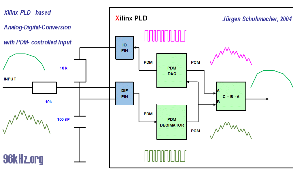
A PDM-based Analog-Digital-Converter using programmable logical devices This design shows an implementation of an ADC using 2 IOs of a programable logical device (PLD). This is often required, because current logical devices do not have an ADC included and interfacing an external ADC required a number of PINs which are mostly limited. Also a low quality is demanded for a lot of applications which can achieved easily by this circuit.
The Pseudo Analog Input
The design is related to my mono amplifier design with analog filter. The design was put into a Xilinx-PLD running at 12.880 MHz clock frequency which is compatible to S/PDIF. A PDM-DAC is built driving an output of the PLD having a low pass filter attached. Doing this an analog voltage is created which acts at a reference for the comparator in the input of the digital circuit. Some modern PLD (FPGAs) do have differential inputs. In case there is none a simple comparator might help. As a result, the input signal is compared with this reference voltage and causes the input of the PLD to toggle creating a PDM-signal which can be put to a decimator. By doing the same with the PDM-output and subtracting them, a mostly artitact free signal is derived. The signal then shall be filtered according to the needs of the particular application. With a 12MHz PDM a typical audio signal (pink
noise) can be sampled with a precision of better than 0,5%. To calibrate the circuit, both low frequency and high frequency behaviour should be trimmed. For non bandwidth limited signals an additional capacitor can be added at the input pin which samples the signal. Please note that the circuit requires manual
calibration in most cases because the switch level of typical
digital pins is not at 50% of the input voltage. For known relations
the 2 Rs giving the REF-voltage can be adapted. In the other case
this has to be compensate by the signal processing. So it has
regarding the balancing of the input, a potential offset of the
voltage and the influence of ESD-diodes when using input levels
close to the rails. Read More Creating Sine Waves with digital devices like PLDs
|
| © 2004 Jürgen Schuhmacher |
