96 kHz.org
Advanced Audio Recording

Introduction to Jitter

This page describes the impact of jitter on high quality audio material. Jitter is always present in digital systems and mostly caused by the analog effects like temperature, voltage instability which affects already frequency synthesis in oscillators at the beginning of the clock path and subsequently also it' processing by e.g. amplifiers and clock drivers.

Clock Driver circuits need to have a low impedance and a very high amplification ratio to generate a steep signal with short rise times to minimize the influence of analog noise (caused by EMI for instance) like shown in image 1. The ideal signal (green) temporarily has a little offset (red) (a small amount of noise) leading to an early point of switching of the input (blue). Regarding a faster rising clock signal in image 2, the effect is significantly lowered.


large additional delay because of noisesmall additional delay because of noise

Also the particular input characteristics of simultaneously triggered devices become more relevant with slow signals. Clock signals feeding different inputs with different switching levels caused by semiconductor doping issues will be processed at slightly different points of time. Image 3 shows an increased switching level of a semiconductor input (in comparison to the ideal 50% point) which leads to a delay. This time gap can cause issues if other parts of the circuit or other devices in an environment do switch earlier. This gap is much smaller with a faster signal like in image 4.

large additional delay because of jittersmall additional delay because of jitter

Typically both mentioned effects do continuously apply in the clock paths in digital systems and if e.g. powering or input characteristics of the clock drivers / clock receivers is insufficient, jitter is introduced and increased.

Generally jitter cannot really be removed since the information of the real point of time is destroyed and hardly can be restored. It is only possible to lower the impact of jitter by decoupling the receiver circuit from the clock and generate a new clock with less jitter which synchronizes to the input only in the long run over a certain period of time. This can be done the analog way with a PLL with a wide input tolerance or digitally by sampling the incoming data and clock and fully decouple from this domain by a asynchronous FIFO.


The negative Impact of Jitter

The point of triggering is important, because when jitter is not fully removed, it directly affects the signal quality by introducing additional harmonics: Starting from a perfect sine wave with 100% linear points of time (x-axis) image 5 the false points of time distort the wave according to the local steepness of the signal like shown in image 6. This applies during recording in ADCs (analog digital converters) as well as in DACs (digital analog converters).

non jittering perfect sine wavestrong jittering sine wave


The negative Impact of Jitter

Jitter being present at the point of sampling time in an ADC, can hardly be removed. If so, the clock has to analyzed in detail and a dynamic resampling has to be applied. For hi-frequent jitter this can be done in a PLD, meaning digital hardware, for low frequent jitter an analysis of the audio material can help. With complex music applications it is possible to measure the frequencies with a FFT and reconstruct the jitter introduced by bad tapes or instable tape speeds. This is best done offline with Software. The analysis can be done in real time making use of a DSP for at least the FFT.


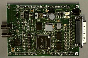
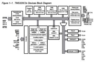
In 1998 some tests had been made with a TMS320-System from Texas Instruments which also is used for my other audio applications. A high speed DSP system is able to produce a small FFT in real time. By comparison of the movement of the frequencies, the average "vibrato" in the music data stream can be measured and trimmed.


Conclusion and Summary

 DSPs can be used to lower the problem of jitter after recording.


© 2000 - Jürgen Schuhmacher